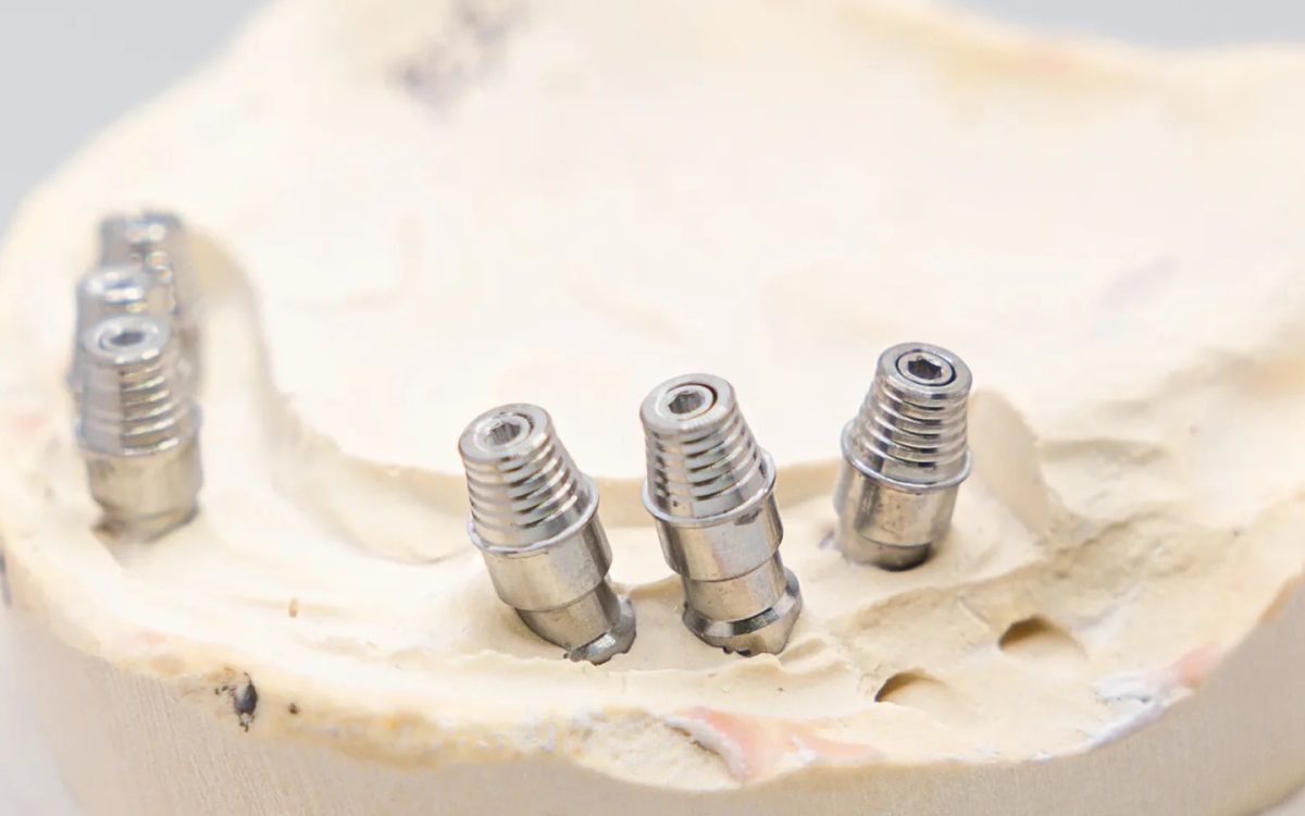
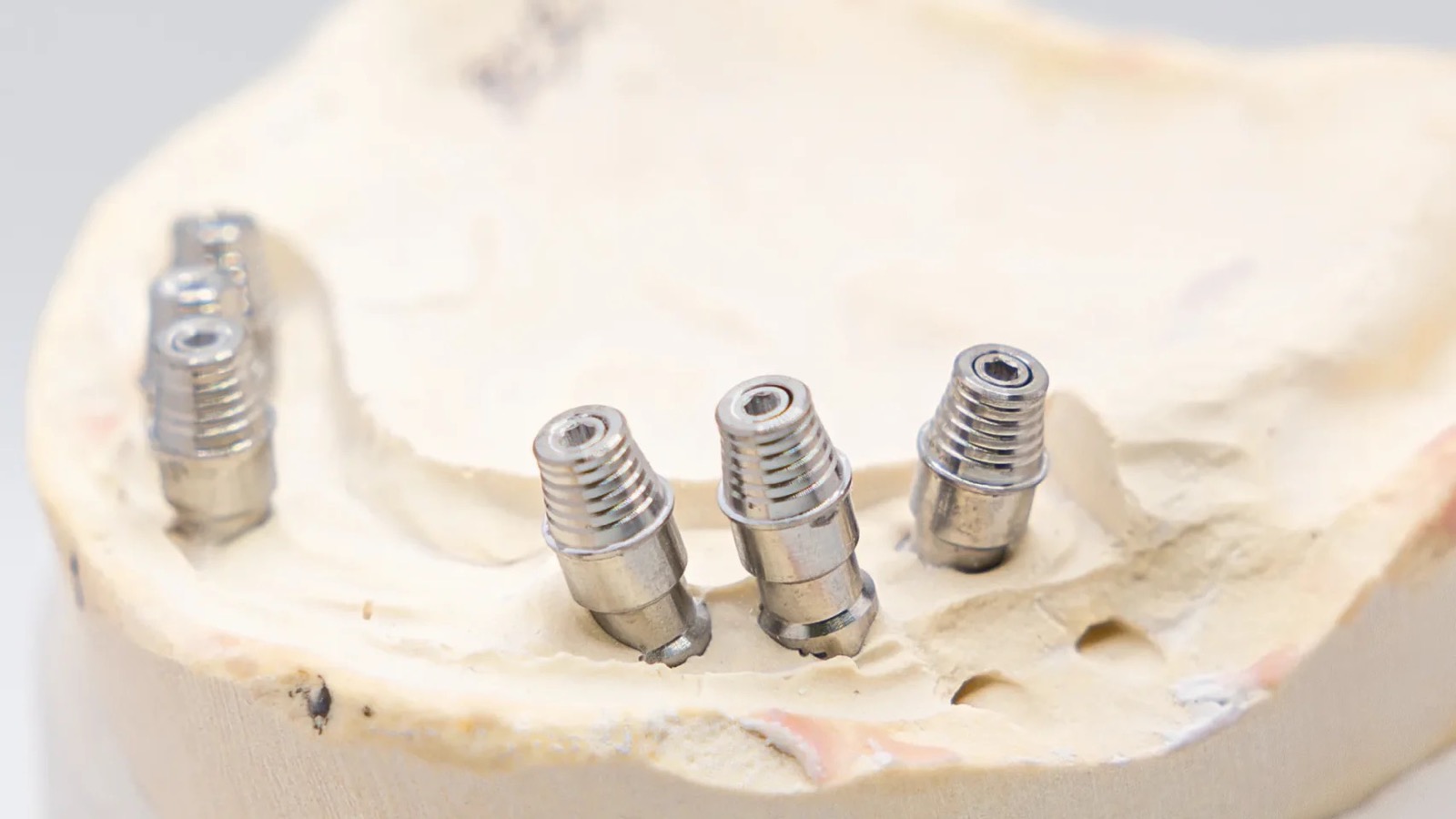
An implant scan body is the part of a digital implant case that decides whether anything else works. It screws into the fixture, the scanner records its shape, and the design software matches that shape against a library file to work out where the implant is and which way it points. Everything we build afterwards is built on that inference.
Which means a worn, wrong or badly scanned component does not produce an obviously bad file. It produces a plausible file that is in the wrong place, and you find out at delivery. Here is what the accuracy research actually blames, and what we need from you.
What an implant scan body does, and what it does not
It is a positional reference, not a measuring device. The scanner never sees the implant. It sees a known object attached to the implant, and the software infers the connection position from it. That inference is only as good as three things: the geometry of the component being what the library says it is, the scan capturing enough of that geometry, and the library file matching the component you actually used.
It is also the digital equivalent of an impression coping, so the same discipline applies. You would not reuse a distorted coping, and the same logic should govern the component in your drawer. The wider scanning workflow is on our intraoral scanners page.
What the research blames, and what it clears
This is the part worth reading twice, because the evidence contradicts what most practices worry about. A systematic review of full arch digital implant impressions found that accuracy varies greatly with interimplant distance, scan body type, scanner type and operator experience, while implant angulation, implant connection and implant depth have no effect.
So the divergent fixture you were nervous about is not the problem. The long empty span between fixtures is. Inaccuracy rises as the scan length grows, because the scanner is stitching overlapping images together and the errors accumulate across the span. That is a scanning strategy problem, not a surgical one.
- Interimplant distance. The longer the edentulous stretch the scanner has to cross, the more stitching error accumulates. Short spans are reliable, long ones are not.
- Scan body type and geometry. Shape, length and top design all measurably affect scanning accuracy.
- Scanner and operator. Both matter, and operator experience is a bigger variable than most people expect.
- Library congruence. The match between the scanned mesh and the library file is its own error source, separate from the scan itself.
- Angulation, connection and depth. Named in the review as having no effect. Worth knowing before you send a case back for a resurgical opinion it does not need.
Scan bodies are consumables, and yours may be worn out
This is the finding practices act on least and should act on most. Scan bodies get autoclaved and reused indefinitely, and they deform while they do it.
A high resolution metrological study measured dimensional change across 50 steam sterilisation cycles. Titanium components showed greater linear deformation at 69.76 microns against 49.50 microns for polymer, while holding angular stability far better, at 0.21 degrees of mean angular change against negative 1.69 degrees in the polymer group. Both materials changed significantly, at p below 0.001. At baseline both were manufactured to a very high standard, with mean linear dimensions around 1.86 microns for the polymer and 1.66 microns for titanium, so the deformation is service wear rather than a manufacturing problem.
Set that against the tolerance you are working to. In vitro work on PEEK components reports trueness and precision generally within 100 microns, which is treated as acceptable for passive implant fit. A component that has drifted by 50 to 70 microns has consumed most of that budget before the scan starts. The practical rule is that these have a service life, polymer components should be treated as shorter lived than titanium in angular terms, and anything visibly marked, scratched or cross threaded should be retired rather than autoclaved again.
What a usable scan looks like
Operator experience is named in the review as one of the variables that genuinely moves accuracy, which is an uncomfortable finding because it means technique is doing more work than equipment. A few things separate a scan we can design from one we have to send back.
- Capture the whole component, including the flat. The anti rotation feature carries the rotational information. If it is not in the scan, the software has position but not orientation, and on a single unit that is the difference between a seated crown and a rotated one.
- Keep soft tissue off it. Tissue creeping over the emergence obscures the base of the component and the software loses the reference where it matters most.
- Scan the arch first, then the component. Establishing the arch gives the scanner a stable frame to stitch the component into rather than asking it to build outward from a shiny cylinder.
- Avoid rescanning over the same area repeatedly. Additional passes over a captured region add stitching noise rather than detail.
- Check the mesh before you send it. Holes, doubled surfaces and a blurred top face are all visible on screen at the chair and none of them improve in transit.
The library has to match the component
Every scan body has a matching library file, and design software finds the implant by fitting that file to the scanned shape. If the library does not match the component, the software still produces a result. It fits the wrong shape to the mesh, lands slightly off, and outputs a restoration that looks correct on screen and does not seat.
That is why the first thing we ask on a scanned implant case is the system, the platform and the scan body manufacturer. A third party component with an original manufacturer library, or the reverse, is one of the few errors in digital dentistry that produces no warning at all. Tell us what is in the mouth and we will use the matching file.
One thing we will always do rather than guess: if the mesh and the library do not fit each other cleanly, we stop and call you. A poor fit between the two is visible to us in the design software even when the scan itself looks fine at the chair, and it is the last point at which the error is cheap to correct.
Where full arch runs out of road
We would rather say this plainly than sell a workflow. The systematic review position on full arch digital implant impressions taken with intraoral scanners is that they are not sufficiently accurate for clinical application, with accuracy varying greatly by the factors above. That is a statement about long spans and accumulated stitching error rather than about digital dentistry generally, and single units and short spans are a different question.
On a full arch case we will therefore ask for a verification step rather than building straight from the scan. A verification jig, a photogrammetry record, or a conventional splinted impression are all reasonable answers depending on what you have. The prosthetic decisions that sit above this are in multi unit abutments, and the retrievability argument is on our screw retained page.
What we need with an implant scan body case
- The implant system, platform diameter and connection, in writing. Not the brand of the scanner, the brand of the implant.
- The scan body manufacturer and reference, so we load the matching library rather than guessing from the mesh.
- Whether the scan is at implant level or abutment level. Those are different files and different restorations.
- A scan that captures the full geometry of the component, including the flat or notch that carries the rotational information. A partially captured scan body is the most common reason we call.
- Adjacent teeth and the opposing arch, plus a bite record. We cannot design an emergence profile against nothing.
- On multiple fixtures, tell us the span. If it is long, we will discuss verification before we design.
If the case is conventional rather than digital, an implant level impression with a splinted coping remains completely acceptable and we take both. What we cannot do is design accurately from a soft tissue level record. Case planning is on for dentists, and what changes end to end is in what a digital dental lab actually changes.
The codes
Scanning is part of the impression rather than a separately reported laboratory procedure, so the codes attach to what gets delivered. A prefabricated abutment is D6056 and a custom abutment is D6057, a distinction covered in custom versus stock abutment. A single implant supported ceramic crown is D6065. Full arch implant supported fixed dentures are D6114 maxillary and D6115 mandibular. Surgical placement of the fixture is D6010.
Reference values only, so confirm against current CDT.
Questions from the prep
How many times can a scan body be autoclaved?
There is no universal number, and the honest answer is fewer than most practices assume. Measurable deformation is documented by 50 cycles in both titanium and polymer. Track them, retire them on a schedule rather than on appearance, and replace anything damaged immediately.
Does implant angulation hurt scan accuracy?
The systematic review says no. Angulation, connection type and implant depth were all found to have no effect on the accuracy of the digital impression. Angulation matters enormously for the restoration, which is what titanium base and multi unit abutment selection are for, but it is not what makes a scan inaccurate.
Titanium or polymer scan bodies?
Both are clinically usable. Titanium holds its angular position better across sterilisation cycles and polymer showed less linear deformation in the same study. If you are scanning long spans where angular error compounds, titanium is the safer choice.
Can you tell from the file if the scan body was worn?
Not reliably, and that is the problem. A worn component produces a clean file in a slightly wrong place. We can see a poorly captured scan and we will call about it. We cannot see wear.
Do I still need a conventional impression as a check?
On single units and short spans, generally no. On full arch, we will ask for a verification step of some kind, because the review evidence on full arch scanning does not support building directly from the scan.
Implant case planning
Send the system and the scan body reference
Tell us the implant system, the platform and which scan body you used, and we will load the matching library before we design. If the span is long we will talk verification first.
Written by Adam Brewer, General Manager, with nearly two decades in the dental implant industry at International Dental Arts. IDA has been a family founded dental laboratory in Tulsa since 1984, working with independent practices across the country. If you want a case reviewed before you commit, get in touch.